


 通过认证
通过认证
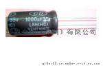
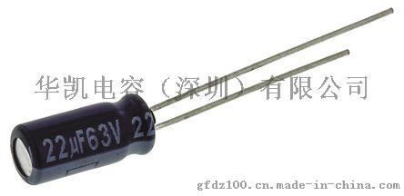
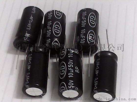
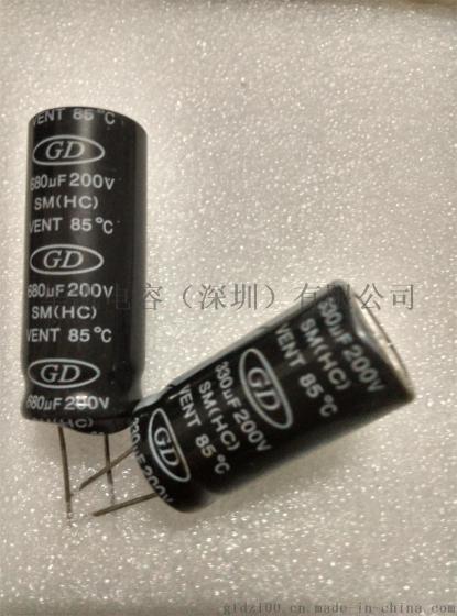
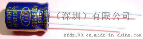
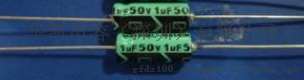
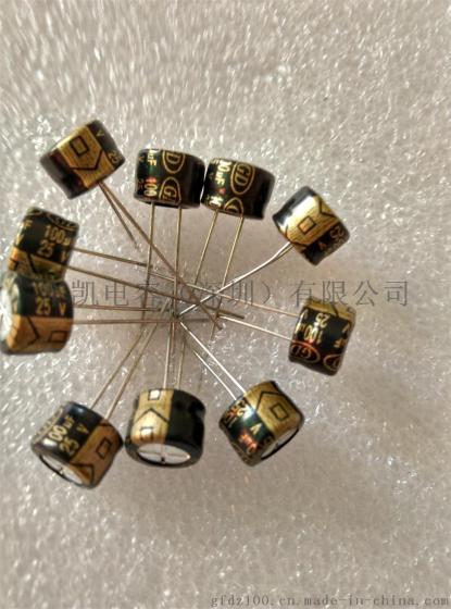
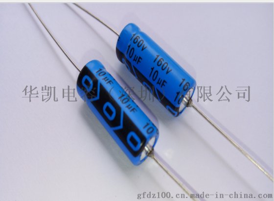
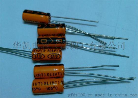
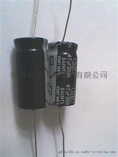
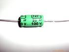
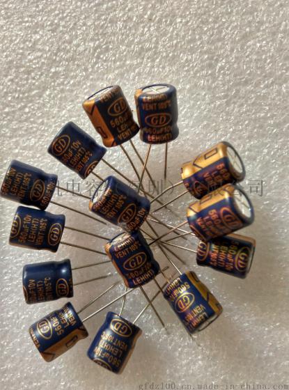
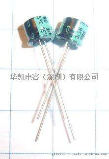
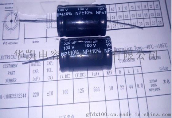
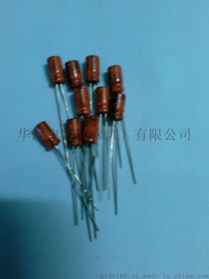
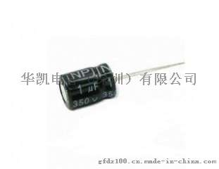
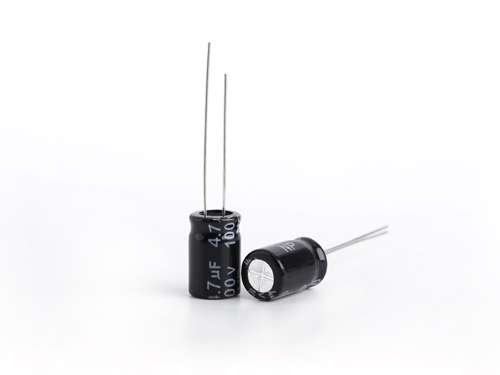
“无极铝电解电容.低容量高电压无极性铝电解电容, BP型为无极品插件电解电容”参数说明
| 是否有现货: | 是 | 认证: | SGS9001 |
| 品牌: | GD | 样式: | 引线式 |
| 结构: | 固定电容器 | 包装方式: | 圆柱形 |
| 工作电压: | 400V | 型号: | NP/BP无极型 |
| 规格: | NP 1uf350v尺寸10x15 | 商标: | GD |
| 包装: | 袋装 | 产量: | 99999999999999 |
“无极铝电解电容.低容量高电压无极性铝电解电容, BP型为无极品插件电解电容”详细介绍
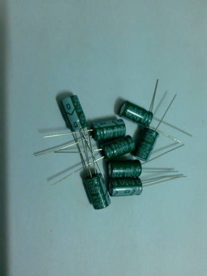
BP型为无极性品,具有低损耗、耐纹波等特性,可用于电视机水平偏转线路及音箱分频器线路中。
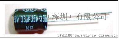
BP无极性标准品
1. 适用于极性反转回路,例如:信号交连或HI-FI高级音响设备如喇叭等。NP series capacitors are suitable for crossover network for HI-FIequipment’s and speakers etc.
2. 具容量误差小,频率响应高之特质。Have excellent frequency characteristic and small deviation ofCapacitance.


BP无极性标准品
1. 适用于极性反转回路,例如:信号交连或HI-FI高级音响设备如喇叭等。NP series capacitors are suitable for crossover network for HI-FIequipment’s and speakers etc.
2. 具容量误差小,频率响应高之特质。Have excellent frequency characteristic and small deviation ofCapacitance.
| Item | Performance Characteristics | |||||||||
| Operating Temperature range使用溫度範圍 | -40 +85ºC | |||||||||
| Rated Voltage額定電壓 | 6.3V ~ 100V | |||||||||
| Capacitance Range容量範圍 | 0.1 µF ~ 2200 µF | |||||||||
| Capacitance Tolerance靜電容量容許差 | +-20% (120Hz, 20ºC) | |||||||||
| Leakage Current洩漏電流 | I< 0.03CV or 3 (mA) whichever is greater after 5 minutes application of rated voltage |
|
||||||||
| Dissipation Factor散逸因數 (120Hz, 20ºC) | Rated Voltage | 6.3 | 10 | 16 | 25 | 35 | 50 | 63 | 100 | |
| tan d (Max.) | 0.26 | 0.24 | 0.22 | 0.20 | 0.16 | 0.14 | 0.15 | 0.15 | ||
| For capacitance of more than 1,000 uF, add 0.02 for every increase of 1,000 uF | ||||||||||
| Temperature Characteristics低溫溫度特性 (120Hz) | Impedance Ratio (120Hz) | |||||||||
| Rated Voltage | 6.3 | 10 | 16 | 25 | 35 | 50 | 63 | 100 | ||
| Z(-25°C)/Z(20°C) | 4 | 3 | 2 | 2 | 2 | 2 | 2 | 2 | ||
| Z(-40°C)/Z(20°C) | 10 | 8 | 6 | 5 | 4 | 4 | 3 | 3 | ||
| Load Life高溫負荷特性 | After2,000 hours application of rated voltage at85°C, capacitors meet the characteristics requirements mentioned below | |||||||||
| Capacitance Change | within 20% of initial value | |||||||||
| tan d | 200% or less of initial specified value | |||||||||
| Leakage Current | Initial specified value or less | |||||||||
| Shelf Life擱置壽命 | After leaving Capacitors under no load at 85°C for 1000 hours and applying voltage according to JIS C-5102 4-3, they meet the specified value for load life characteristics listed above | |||||||||
| WV(SV)Cap(mF) | 6.3 (8) | 10 (13) | 16 (20) | 25 (32) | 35 (44) | 50(63) | 63 (75) | 100 (125) | ||||||||
| 0.1~0.47 |
|
|
|
|
|
|
|
|
|
|
5 x 11 |
|
5 x 11 |
|
5 x 11 |
|
| 1 |
|
|
|
|
|
|
|
|
|
|
5 x 11 | 10 | 5 x 11 | 10 | 5 x 11 | 18 |
| 1.5 |
|
|
|
|
|
|
|
|
|
|
5 x 11 | 15 | 5 x 11 | 15 | 5 x 11 | 21 |
| 2.2 |
|
|
|
|
|
|
|
|
|
|
5 x 11 | 23 | 5 x 11 | 23 | 5 x 11 | 29 |
| 3.3 |
|
|
|
|
|
|
|
|
|
|
5 x 11 | 28 | 5 x 11 | 32 | 5 x 11 | 35 |
| 4.7 |
|
|
|
|
|
|
|
|
5 x 11 | 31 | 5 x 11 | 33 | 6.3 x 11 | 45 | 8 x 11 | 64 |
| 10 |
|
|
|
|
5 x 11 | 39 | 5 x 11 | 41 | 5 x 11 | 45 | 6.3 x 11 | 52 | 6.3 x 11 | 57 | 8 x 11 | 71 |
| 22 |
|
|
5 x 11 | 55 | 5 x 11 | 58 | 6.3 x 11 | 65 | 6.3 x 11 | 73 | 6.3 x 11 | 89 | 8 x 11 | 96 | 10 x 15 | 135 |
| 33 | 5 x 11 | 65 | 5 x 11 | 68 | 5 x 11 | 71 | 6.3 x 11 | 80 | 8 x 11 | 100 | 8 x 11 | 105 | 10 x 12 | 135 | 13 x 20 | 200 |
| 47 | 5 x 11 | 78 | 5 x 11 | 81 | 6.3 x 11 | 91 | 6.3 x 11 | 95 | 8 x 11 | 120 | 10 x 12 | 150 | 10 x 16 | 180 | 13 x 20 | 240 |
| 100 | 6.3 x 11 | 120 | 6.3 x 11 | 125 | 8 x 11 | 150 | 8 x 11 | 160 | 8 x 12 | 225 | 10 x 20 | 265 | 13 x 20 | 320 | 16 x 25 | 425 |
| 220 | 8 x 11 | 205 | 8 x 11 | 215 | 8 x 12 | 260 | 10 x 16 | 300 | 13 x 20 | 415 | 13 x 25 | 480 | 16 x 25 | 575 | 18 x 36 | 725 |
| 330 | 8 x 11 | 255 | 10 x 16 | 340 | 10 x 16 | 355 | 13 x 20 | 455 | 13 x 20 | 510 | 16 x 25 | 650 | 16 x 32 | 755 |
|
|
| 470 | 10 x 12 | 350 | 10 x 16 | 405 | 10 x 20 | 460 | 13 x 20 | 545 | 13 x 25 | 655 | 16 x 32 | 835 | 18 x 36 | 1050 |
|
|
| 1000 | 10 x 20 | 615 | 13 x 20 | 720 | 13 x 25 | 815 | 16 x 25 | 950 | 16 x 32 | 1140 |
|
|
|
|
Case Size | Allow-ableRipple |
| 2200 | 13 x 25 | 1070 | 16 x 25 | 1230 | 16 x 32 | 1380 | 18 x 36 | 1540 |
|
|
|
|
|
|
||